Today we are discussing the principle of a potentiometer. And also see how a potentiometer works. Before all this, let us know what is potentiator and where do we use it.
A potentiometer is a three-terminal resistor having either sliding or rotating contact that forms an adjustable voltage divider. Out of the three terminals - one is varying, whereas the rest two are fixed.
The Potentiometer is an electric instrument used to measure the EMF(electromotive force) of a given cell, the internal resistance of a cell. It is the device used to compare the EMF of two cells. It connects with a cell whose emf is known or other supply sources. Comparing an unknown voltage with a known one gives you an unknown voltage.
So we got to know what is a potentiometer and we will talk about its use in the last, Now let's see how it works, and what is the principle of a potentiometer
More About Potentiometer
- The potentiometer is also known as an Ideal voltmeter. As it gives accurate answers.
- The potentiometer is a highly sensitive device.
- The potentiometer possesses infinite resistance.
- The working of the potentiometer is based on the null method i.e. i = 0, This condition makes the potentiometer, an ideal Voltmeter.
The potentiometer is used for many purposes :
- To measure the EMF of the cell.
- To measure the terminal Potential difference of the Cell.
- To measure the internal resistance of the cell.
- To compare the EMF of two cells.
However, the most common use of potentiometers is to control electrical devices such as volume controls on audio equipment.
Principle of a Potentiometer
The principle of a potentiometer is the potential difference between any points is directly proportional to the length of the wire between those points.
V ∝ L
Proof:
As per Ohm's law
V = IR
R = ρl/A
V = Iρl/A
With ρ and A constants, I is also a constant for a rheostat.
V = KI
V ∝ l
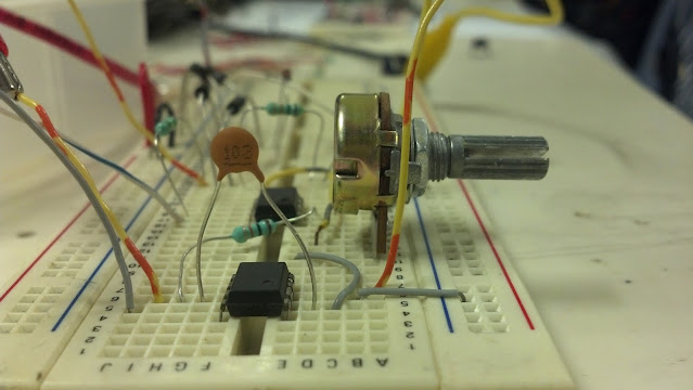
Construction of a Potentiometer
The potentiometer consists of a long resistive wire L made of magnum or constantan (reason for the selection of a magnum or constantan here is that the alloy has a high resistivity and a low-temperature coefficient) and a battery of known emf E. This voltage is called the driver cell voltage. Connect the two ends of the resistive wire L to the battery terminals as shown below; Let us assume this is an elementary circuit arrangement.
One terminal of the second cell (whose emf E is to be measured) is at one end of the primary circuit and the other end of the cell terminal is connected through galvanometer G to any point on the resistive wire. Now suppose this arrangement is a secondary circuit.

Always Remember
- Driver Cell should always be stronger than the Driven cell.
- The Positive terminal of the Driver cell must be connected to the positive terminal of the Driven cell.
- Current through the potentiometer wire should remain constant.
- The Potentiometer wire should be of the uniform area of cross-section.
Working of a Potentiometer
When Cell E1 is put in the circuit as shown above figure with the jokey attached to the corresponding length. Since the potential difference is zero (0) and there is no flow of current, the galvanometer has zero detection. So, let x be the length of the null point. let us consider the null point is at point P
As per the principle of the potentiometer
E1 ∝ x
E1 = Kx
Since the EMF of two cells can also be compared, Let the first cell of EMF E1 be given a null point at length = L1 and the second cell of EMF E2 shows a null point at length = L2. Therefore,
E1/E2 = L1/L2
When an auxiliary circuit is connected to cell E1, this cell E1 is in use. Now the Null length would be slightly lesser than the previous case.
V1 ∝ l2
V1 = Kl2
V1 = E x l2/ltotal

In Principle of a Potentiometer, After working of a potentiometer topic, now we will see the types of potentiometer
Types of Potentiometers
We already know that potentiometer has three terminal connections. Most potentiometers have a wiper that rotates over an arc-shaped resistive material. However, in some other types of potentiometers, the wiper slides linearly over a straight resistive strip.
Based on the concept of the resistive strip, there are two main types of potentiometer:
- Rotary Potentiometers
- Linear potentiometers
Although the basic construction characteristics of these potentiometers are different, the working principle of these two types of potentiometers is the same.
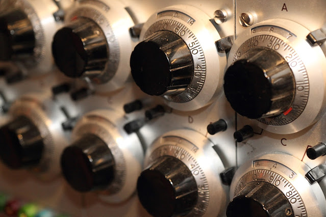
Rotary Potentiometers
These are the most common type of potentiometer, where the wiper moves along a circular path. Rotary type potentiometers are mainly used to obtain adjustable supply voltages in a part of electronic circuits and electrical circuits.
This type of potentiometer has two terminal contacts between which a uniform resistance is placed in a semi-circular pattern. The device also has a middle terminal that is connected to the resistance via a sliding contact connected to a rotary knob. The sliding contact can be moved over a semi-circular resistance by rotating the knob. The voltage is taken between a resistance end contact and a sliding contact.
Linear Potentiometers
This Potentiometer is like the Rotary potentiometer but the only difference is that here instead of rotary movement the wiper moves along a straightway. The connection of the two terminals of the resistor is connected to the voltage source. The sliding contact on the resistor can be slid through the track attached to the resistor. The sliding terminal of the resistor is connected to one end of the output circuit and another terminal is connected to the other terminal of the output circuit.
This type of potentiometer is for the most part used to detect voltage in a circuit, to measure the internal resistance of a battery cell, to compare a battery cell with a standard cell.
Application of Potentiometers
There are many applications of Potentiometer are :
- Audio Control: Both linear and rotating potentiometers are commonly used for frequency attenuation, volume adjustment, and other audio signal features.
- Television: Picture brightness, contrast and colour response were all controlled by means of a potentiometer.
- Transducers: To measure the displacement of the body, which is portable, is attached with a sliding component located on the potentiometer.
- Potentiometer as Voltage divider: A set input voltage mounted on both ends of the potentiometer can be used as a voltage divider to create a manually adjustable output voltage on the slider.
That's all I had to tell you about the principle of the potentiometer and stay with us to keep reading such articles.
Comments
Post a Comment
If you have any doubt,let me know